Async Modem Line Control
Order Number: M753
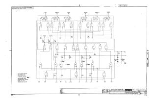
Summary: This document is a technical schematic for a Digital Equipment Corporation (DEC) Async Modem Line Control circuit (M753). The diagram illustrates the logic gate configuration, using components such as DEC7400N, 7401N, and 7474N ICs, to manage various modem control signals. Key interface signals featured in the circuit include "Rost to Send," "Term Rdy," "Carrier," "Ring," and "Clear to Send/Data Set Ready." The schematic details the interconnections between these logic gates, resistors, capacitors, and diodes, defining the flow of control signals for modem communication operations.
Site structure and layout ©2025 Majenko Technologies