Punch Control M710
Order Number: M710
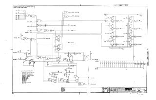
This document is a technical schematic for the Digital Equipment Corporation "Punch Control M710" module. The schematic details the logic circuitry, including various integrated circuits (such as DEC7474, DEC9601, and DEC7400), capacitors, resistors, and diodes required for punch control operations. It includes specific signal paths for I/O functions, clock pulses (A and B), synchronization, and motor timing delays (ranging from 1/3 second to 5 seconds). The document also provides specifications for components used in the assembly, notes regarding power (PIN 14 = +5V, PIN 7 = GND), and a reference conversion chart for transistors and diodes.
Site structure and layout ©2025 Majenko Technologies