I/O Device Select M592
Order Number: M592
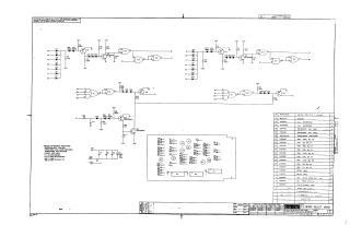
This document is a technical schematic for an "I/O Device Select" circuit board (M592), produced by the Digital Equipment Corporation in 1971. The schematic illustrates a logic circuit configuration using various transistors, diodes, resistors, and integrated circuits (specifically DEC1074H50 and DEC1074H00).
Key features include:
- Circuit Logic: The diagram details multiple signal inputs (A1–H1, V2, T2, etc.) routed through logic gates and transistor-based switching stages to provide specific outputs.
- Component Specifications: A parts list is included, detailing specific values for capacitors (0.01μF and 39μF), resistors (ranging from 22Ω to 100kΩ), and diodes (D664 and D662).
- General Notes: The document specifies that unless otherwise indicated, resistors are 1/4W 5%, capacitors are 0.01μF/100V, and integrated circuits use pin 7 for ground and pin 14 for +5V.
- Documentation: It includes a "Transistor & Diode Conversion Chart" to assist with component identification and cross-referencing.
Site structure and layout ©2025 Majenko Technologies