Bus Converter M517
Order Number: M517
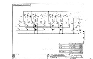
This document is a technical schematic for a Digital Equipment Corporation "Bus Converter M517," dated 1970. The diagram details the circuit layout, which consists of a transistor and diode matrix. The schematic includes a comprehensive parts list, providing specific values for resistors (R1 through R38), capacitors (C1, C8, and C9), transistors (Q1 through Q20), and various diodes (D1 through D30), along with their corresponding Digital Equipment Corporation part numbers. The document also includes a transistor and diode conversion chart.
Site structure and layout ©2025 Majenko Technologies