Positive Bus Receiver
Order Number: M511
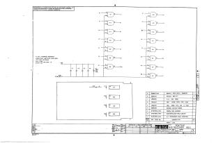
This document is a technical schematic for the Digital Equipment Corporation "Positive Bus Receiver" (Model M511). It details the electronic circuitry, which utilizes four DEC 380A integrated circuits to process signals.
Key information provided includes:
- Circuit Design: The schematic shows the input/output logic paths for various signals (E1, F1, B1, J2, L1, F2, H1, R1, S1, M2, M1, T2, U2, P2, R2).
- Specifications: The document specifies that unless otherwise noted, capacitors are .01uF (100V, 20%) and all ICs are DEC 380A models, with Pin 1 for ground and Pin 8 for +5V.
- Parts List: A comprehensive table lists the necessary components, including the etched circuit board, four DEC 380A ICs, various capacitors (including one 39uF tantalum capacitor), mounting hardware (eyelets), and a magenta flip-chip handle.
- Administrative Details: The document includes references to associated production documentation, such as the module ECO history, assembly/drilling hole layout, and X-Y coordinate hole locations.
Site structure and layout ©2025 Majenko Technologies