Bus Converter M508
Order Number: M508
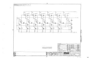
This document is a technical schematic for a Bus Converter (Model M508), copyrighted by Digital Equipment Corporation in 1968. The diagram illustrates a transistor-based logic circuit consisting of an array of transistors (Q1, Q3, Q4, Q6–Q16), various diodes (D1–D28), and a network of resistors (R1–R25) and capacitors (C1–C4). The accompanying parts list details the specific components used, including resistor values, diode types, and transistor specifications required for the maintenance and assembly of the converter module.
Site structure and layout ©2025 Majenko Technologies