Variable Clock M401
Order Number: M401
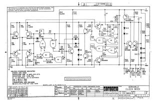
This document is a technical schematic for the "Variable Clock M401" module, manufactured by the Digital Equipment Corporation in 1967. The circuit is designed to generate positive and negative pulse outputs.
Key technical details provided in the schematic include:
- Components: The design utilizes specific transistors (DEC4258, 2N4274, DEC3009B, DEC6534D) and integrated circuits (DEC7400 and DEC74H00).
- Specifications: Unless otherwise noted, the schematic specifies that diodes are D662, capacitors are .01 MFD (100V, 20%), and resistors are 1/4W (5%).
- Configuration: It details pin assignments for the ICs (Pin 7 for GND, Pin 14 for +5V) and includes a variable component (R8, a Helitrim potentiometer).
- Power Requirements: The circuit operates on a +5V supply and includes various decoupling capacitors for signal stabilization.
The document also features a transistor and diode conversion chart and a revision history, indicating it is a proprietary design intended for test and maintenance purposes.
Site structure and layout ©2025 Majenko Technologies