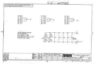
3-8 Input Nand Gate
Order Number: M139
This document is a technical schematic for the Digital Equipment Corporation M139 3-8 Input NAND Gate module, dated 1969. The schematic details the configuration of three logic gates (E1, E2, E3), each featuring eight inputs. It also specifies standard power requirements and component values, noting that all integrated circuits (ICs) used are DEC1074H30 models. The document specifies that pin 7 of each IC is connected to ground, while pin 14 is connected to +5V. Additionally, it outlines the specifications for peripheral components, including resistors (1/4W, 5%) and capacitors (.01 MFD, 100V, 20%), and includes a bypass capacitor (C5) rated at 39 MFD, 10V.
Site structure and layout ©2025 Majenko Technologies