Photo Transistor Amplifier G918
Order Number: G918
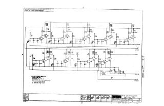
This document is a technical schematic for the Digital Equipment Corporation "Photo Transistor Amplifier G918," dated April 1969. The circuit diagram details the electrical configuration of the amplifier, including a complex arrangement of transistors (specifically 2N3646 models), resistors, capacitors, and diodes (D664).
Key features of the schematic include:
- Components: The design utilizes a large array of resistors, capacitors, and multiple transistors to manage signals.
- Specifications: The document notes that unless otherwise indicated, resistors are 1/4W 5%, capacitors are 0.01µF 100V 20%, and diodes are D664.
- Connectivity: The circuit includes power inputs for +5V and -15V, as well as an AC ground, an output point, and a threshold test point.
- Conversion Chart: A provided conversion chart lists standard EIA equivalents for the proprietary transistors and diodes used in the design.
- Proprietary Notice: The schematic is intended strictly for test and maintenance purposes and is protected by copyright.
Site structure and layout ©2025 Majenko Technologies