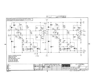
Xy-Control G917
Order Number: G917
This document is a technical schematic diagram created by the Digital Equipment Corporation in 1969 for an XY-Control module (G917). The circuit utilizes two MC1520G operational amplifiers (labeled E1 and E2) to manage input and output signals. The schematic details the configuration of various resistors, capacitors, and diodes (D664, D662) used to maintain signal integrity and control. It includes specifications for component values, such as capacitor voltage ratings, diode conversions, and resistor tolerances, and is intended solely for test and maintenance purposes.
Site structure and layout ©2025 Majenko Technologies