Power Supply Bi G817
Order Number: XX-XXXXX-XX
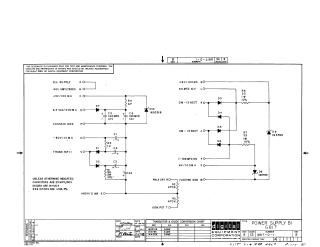
This document is a technical schematic for the Digital Equipment Corporation Power Supply G817 (Revision B), dated 1969. The circuit diagram illustrates the configuration of various power supply outputs, including H.V. supply, unfiltered 40V, and various low-voltage regulated outputs (+5V, +6V, -80V).
Key components noted in the schematic include:
- Capacitors: 190 MFD 12V electrolytic capacitors and general-purpose 25 MFD 150V capacitors.
- Diodes: Includes IN5231B, IN3785, and IN4004 (general diode type).
- Resistors: Standard power resistors (33-ohm 1W) and high-resistance dividers (470K) for voltage regulation and potentiometer adjustment.
- Annotations: The document includes a "Transistor & Diode Conversion Chart" and specifies that the schematic is intended for test and maintenance purposes, noting that the circuits are proprietary to the Digital Equipment Corporation.
Site structure and layout ©2025 Majenko Technologies