Power Distribution Board Control
Order Number: XX-XXXXX-XX
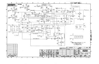
This document contains the technical engineering schematics and printed circuit board (PCB) layouts for the "BA8-C Power Distribution Board Control." It includes:
- Schematic Diagram: A detailed electrical circuit diagram showing the component connectivity, including power inputs, fan control, "Power OK" signaling, battery monitoring, and various charge-cycle timing circuits. It specifies component types and operational notes.
- Component Placement: An assembly-view diagram showing the physical location of components on the board, including resistors, capacitors, integrated circuits, and relay mounting instructions.
- PCB Layouts: Top and bottom side copper trace layouts for the board, identifying the routing patterns for the circuit.
- Specifications: The documentation includes revision history, assembly notes (such as hardware installation procedures for relay K1), and standard engineering references for the Digital Equipment Corporation power distribution hardware.
Site structure and layout ©2025 Majenko Technologies