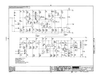
Disc Read Amp and Slice G085
Order Number: XX-XXXXX-XX
This document contains technical engineering schematics for the Digital Equipment Corporation "Disc Read Amp and Slice G085" circuit board.
The document consists of two parts:
- Circuit Schematic: Detailed electrical diagram showing the configuration of transistors (Q1–Q18), diodes (D1–D38), capacitors (C1–C16), and resistors (R1–R60). The schematic details power requirements (+20V, -15V), signal inputs (AVO, AM, BS, BT), and outputs (AE, AU, OAT, BE, BO, BRO).
- Component Layout: A board-level diagram illustrating the physical placement and arrangement of all resistors, transistors, diodes, and capacitors on the G085 printed circuit board to assist in assembly and troubleshooting.
Site structure and layout ©2025 Majenko Technologies