KDJ11-A Configuration Guide
Order Number: EK-KDJ1A-CG
This document, the KDJ11-A Configuration Guide, details how to configure the KDJ11-A module using its nine user-selectable jumpers and how to interpret its four diagnostic LEDs for troubleshooting.
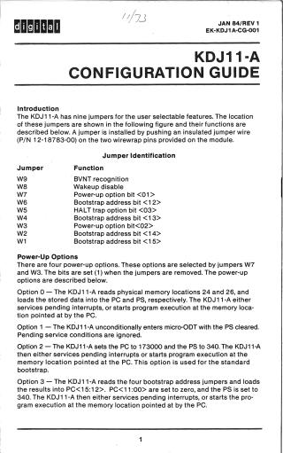
Jumper Configuration: The KDJ11-A module's features are set by installing or removing specific jumper wires (W1-W9). Key functions controlled by jumpers include:
- Power-Up Options (W3, W7): These two jumpers select one of four power-up modes (0-3). The options dictate the initial Program Counter (PC) and Processor Status (PS) register values, defining behaviors like reading from specific memory locations, entering micro-ODT, or initiating a standard or user-defined bootstrap. A bit is set (1) when the corresponding jumper is removed.
- Boot Address (W1, W2, W4, W6): When Power-Up Option 3 (user bootstrap) is selected, these four jumpers determine the high four bits (15:12) of the PC, allowing the user's bootstrap program to start at a specified 2048-word boundary. A bit is set (1) when the corresponding jumper is installed.
- HALT Option (W5): This jumper controls the module's behavior after a HALT instruction in kernel mode. If removed, the KDJ11-A traps to location 4; if installed, it enters micro-ODT mode.
- Wakeup Disable (W8): This jumper enables or disables the on-board wakeup circuit, which is crucial for proper BDCOK signal sequencing. The wakeup circuit is enabled when the jumper is removed.
- BEVNT Recognition (W9): This jumper controls the recognition of the LSI-11 bus BEVNT (external event interrupt). Recognition is enabled when the jumper is removed.
The document also provides the module's Factory Configuration (default jumper settings) for review.
Diagnostic LEDs (D1-D4): Four LEDs provide status monitoring and aid in troubleshooting:
- D1: Illuminates when the module is operating in micro-ODT mode.
- D2-D4: Used during power-up diagnostics. They light up at the start and turn off upon successful diagnostic completion. Specific LED states indicate probable failures:
- D2: Failure to read/write to the CPU Error register (microcode not running).
- D3: Console terminal not responding (timeout on a specific memory location).
- D4: Memory system not responding (timeout on memory access). The guide includes a table to help identify system failures based on the combined on/off status of these LEDs.
Site structure and layout ©2025 Majenko Technologies