Vr201
Order Number: XX-A459E-C9
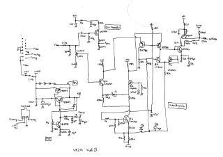
This document comprises a four-sheet schematic diagram detailing the circuitry for a Cathode Ray Tube (CRT) display system, likely a monitor or television.
Sheet 1 (PSU, Video Amplifier, Sync Separator): This section describes the Power Supply Unit (PSU) that generates various regulated voltages (+9V, +12V, +12V5, 10V). It also includes the video input processing, featuring a contrast control, a sync separator (using a ZN3906 transistor), and a multi-stage video amplifier built with 2N3906, 2N3904 transistors, and LM3046 ICs. Keyboard-related input/output circuitry is also present.
Sheet 2 (Horizontal Sync): This sheet focuses on the horizontal synchronization circuit, which is primarily controlled by a TDA1180 integrated circuit. It takes sync input and generates precise flyback and line drive signals, which are then amplified by an NSDU05 transistor to manage horizontal deflection timing.
Sheet 3 (Vertical Scan): This section details the vertical deflection circuitry, centered around a TDA1170S integrated circuit. This IC receives vertical sync signals, produces ramp waveforms, and drives the vertical deflection yoke. It incorporates controls for adjusting height and vertical linearity, and includes connections for dynamic focus.
Sheet 4 (Line Output Stage & CRT): This final sheet illustrates the high-voltage generation and horizontal output stage, which powers the CRT. Key components include a flyback transformer responsible for generating Extra High Tension (EHT) and other high voltages (e.g., 640V, 560V, 200V), along with an MJE13006 transistor for horizontal output. The diagram shows detailed connections to the CRT for EHT, screen grid (G2), control grid (G1), RGB cathodes, and includes controls for brightness, focus, and width.
Site structure and layout ©2025 Majenko Technologies