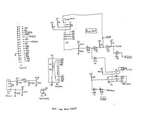
RD51 Logic Board and Spindle Motor PCB Schematics
Order Number: XX-53353-12
This document contains a series of nine schematic diagrams detailing the design of the RD51 system, specifically covering its logic board and spindle motor control PCB.
The first seven sheets focus on the Logic Board:
- Sheet 1 (Control): Illustrates the main control interface (J1) with various input/output signals (e.g., Index, Ready, Step, WrFault), along with drive select logic using a jumper block and associated gates, and the initial index sensor circuitry. Power connections are also shown.
- Sheet 2 (Microcontroller Interface and Seek Control): Details the microcontroller (E21) and its peripheral connections, including ports for control signals, CPU ready status, and seek/step control logic. Power OK sensing is also depicted.
- Sheet 3 (Index/Track 0 & Head Stepper): Shows advanced index signal processing, ready signal generation, Track 0 sensing circuitry, and the interface to the Head Stepper motor, outlining its phase connections.
- Sheet 4 (Stepper Driver): Provides detailed power driver circuitry for the stepper motor, including individual control for four phases (DA+, DA-, DB+, DB-) with associated hold and clamp signals, using various transistors and logic gates.
- Sheet 5 (Data & Write Control): Presents the data interface (J2), including signals for data selection (D.Selctd) and read/write paths. It covers the write data path, write fault detection, and components for read signal conditioning.
- Sheet 6 (Head Select & Head Switch): Contains logic for selecting specific read/write heads, generating appropriate head drive signals (Hd0-Hd3), and managing read/write data lines to the heads. It also includes circuitry for a "Select Error" indication.
- Sheet 7 (Read Data Path): Focuses on the extensive conditioning, amplification, and buffering of the read data signal (RdD) to produce the final RDout signal.
The remaining two sheets cover the Spindle Motor PCB:
- Sheet 8 (Spindle Motor Commutation and Brake): Outlines the drive circuitry for the spindle motor, including commutation signals and the transistors responsible for driving the motor coils. It also features the Power-Down Brake mechanism.
- Sheet 9 (Speed Control): Illustrates the feedback control loop for the spindle motor speed. This includes a SpeedSense input, operational amplifiers, and transistors to regulate the motor's speed and generate a brake control signal.
Collectively, these schematics provide a comprehensive electrical blueprint of the RD51 system's control logic, motor driving, and data handling capabilities.
Site structure and layout ©2025 Majenko Technologies