LK201 Keyboard Circuitry and Key Matrix
Order Number: XX-FF9EF-2A
This document set details the design and key matrix for an LK201 keyboard. It comprises multiple sheets outlining the electronic components and keyboard layout.
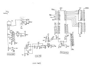
The first sheet focuses on the core control circuitry, featuring an 8051 microcontroller (E1) with associated power regulation (7805, -12V PSV), serial communication interfaces (RxD, TxD), and connections for various keyboard control signals such as Volume, Beep, Wait, Comp (Compare), Lock, and Hold. It also includes the crystal oscillator (X1, X2) for the microcontroller's clock and a 555 timer for an unspecified function.
The second sheet details the output indicators and sound generation. It shows the drive circuits for Hold, Lock, Comp, and Wait LEDs, each controlled by transistors. Additionally, it illustrates the beeper circuit, which responds to Beep and Volume signals, utilizing another 555 timer and transistors to produce audio feedback. This sheet also outlines the keyboard tail connectors (J1, J2, J3) which interface with the key matrix.
The third sheet presents a visual layout of the keyboard's key matrix, showing the physical arrangement of keys. This includes a comprehensive set of alphanumeric characters, punctuation, function keys (F1-F20), navigation keys (arrows, Home, End), and special keys (e.g., Ctrl, Shift, Tab, Return, Select, Help, Delete, Insert).
The final two sheets provide detailed logical mappings of the key matrix. These tables correlate specific key functions (e.g., "ENTER", "SPACE", "print screen", "SHIFT", "CTRL") with their respective row and column intersections, each assigned a unique alphanumeric code. These mappings are crucial for the microcontroller to interpret key presses and include a note regarding phantom key avoidance.
Site structure and layout ©2025 Majenko Technologies