Rainbow Hard Disk Controller
Order Number: XX-E414A-FA
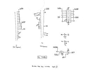
This document is a multi-page schematic diagram detailing the design of a Rainbow Hard Disk Controller. It illustrates the various functional blocks and their interconnections, encompassing both digital logic and analog circuitry.
The controller interfaces with a host system via expansion bus connectors (J1, J4) for system data, addresses, and control signals like reset, interrupt, read, and write (Page 1). The core of the design revolves around a WD1010-00 hard disk controller IC (E42), which manages data transfer (HDC Data) and generates various drive control signals such as RWC, SeekComp, Trk00, Write Fault, Index, DRdy, Step, and Dir (Page 2). A data buffer RAM (E52) is included for temporary storage of hard disk data, with associated port address decoding (E54, E516) and buffer address generation logic (Page 3).
The document also details logic for reading drive status (e.g., Dr-Sel, HS0-HS2, WE, Wr-Fault, DRdy, Trk00) through status ports (Page 4), and drive buffering for signals being sent to the hard disk drive (Page 5). Critical components for data recovery and clocking include write precompensation (E22, E16), read clock generation (VCO, flip-flops on Page 6), and a phase comparator (Page 7) for synchronizing read data pulses. An analog section provides the Voltage Controlled Oscillator (VCO) and its control voltage generation circuitry, crucial for precise timing in read operations (Page 8). Finally, the document provides the pinout and signal assignments for the Rainbow Hard Disk Cable connecting the controller to the hard drive (Page 9). The design utilizes a mix of discrete TTL logic gates, flip-flops, buffers, and a dedicated hard disk controller integrated circuit.
Site structure and layout ©2025 Majenko Technologies