Rainbow Graphics Card
Order Number: XX-E0EF0-9F
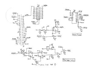
This document provides a detailed set of circuit diagrams and accompanying logic equations for a "Rainbow Graphics Card," a video display adapter system. It is composed of fourteen circuit diagram sheets and one sheet outlining programmable logic array (PAL) equations.
The card's architecture is structured around several interconnected functional blocks. It manages data and address flow through a system of bidirectional buffers (e.g., "Butt Data," "Sys Data"), with address decoding handled by various logic components to generate control signals like RAS, LDBIn, and read/write enable. A central "Master Clock" and a series of control registers and flip-flops generate essential timing signals (e.g., SRMClk, GOCLIR, ALE) and manage the card's major operational states and control ports.
Extensive memory subsystems are integrated, including main RAM, a dedicated Video RAM (using 64Kx1 DRAMs) for display data, and an "Update Buffer" for managing incremental screen changes. A Memory Management Unit (MMU) is crucial for address translation and routing data between these different memory areas. The card also features a Graphics Display Controller (GDC) interface, which handles GDC data, address lines, and read/write operations for the external display controller.
Video output generation involves a "Colour Look-up Table" (CLUT), which translates pixel data into specific RGB color values. Video shift registers then serialize this parallel data into a stream for display. The final "Video Output" stage utilizes Digital-to-Analog Converters (DACs) and resistor networks to produce analog Red, Green, and Blue (RGB) video signals, alongside horizontal and vertical synchronization outputs for connection to a monitor.
The concluding sheet provides JEDEC file output, detailing the Boolean equations implemented within a PAL16L8, indicating custom logic for specific control functions such as "Updatien Ortoma Xorteam" (Update OR-term XOR-term) and data manipulation.
Site structure and layout ©2025 Majenko Technologies