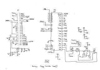
Rainbow Floppy Controller Schematic
Order Number: XX-FB0D9-64
This document contains a six-sheet schematic diagram detailing the design of a Rainbow Floppy Controller.
Sheet 1 depicts the core Floppy Disk Controller (FDC) integrated circuit, identified as a 1793 (E25), which is a common WD1793-compatible FDC. It shows the interface to data and address buses, various control signals (e.g., FDCIn, FDCOut, Ready, Step, Dir, Irq, ProgRst), and the generation of multiple clock frequencies (4MHz, 2MHz, 500kHz) supplied to the FDC. This sheet also includes a primary J1 connector for external interface signals.
Sheet 2 focuses on the floppy drive connectors (J2 for Drive A-B, J3 for Drive L-D) and their associated signals. It illustrates the individual control and data lines for each drive, such as Index, Select, Motor On/Off, Direction, Step, Write Data, Track 00, Write Protect, Read Data, Side Select, and Drive Ready. A "Drive Status" block is also indicated.
Sheet 3 details the control and status ports. It includes logic using a latch (E19) to control motor activation, side selection, and Force Ready signal based on FDC output. A multiplexer (E16) is used for drive selection. Buffers (E13) are shown for inputting various drive status signals back to the FDC, and gates handle the individual drive select and motor control signals for each drive.
Sheet 4 outlines the write precompensation and read data paths. The write precompensation circuit conditions the write data (WD) with "Late" and "Early" signals from the FDC and a clock (Foclk) before generating "Precomp Data". The read data path shows the initial processing of the raw read data (DrRd), including the VFOE (Variable Frequency Oscillator Enable) signal, culminating in the "RawRd" output.
Sheet 5 presents the data separator, a crucial part of the read process. This circuit, utilizing flip-flops (E26a, E26c, E9a, E9b) and a CA3130 operational amplifier, forms a Phase-Locked Loop (PLL) based VCO (Voltage Controlled Oscillator) for recovering the clock and data from the "RawRd" signal. It produces signals like "Rclk2" and "VCOCTR" for precise data extraction.
Sheet 6 provides the detailed schematic of the Read Clock VCO (Voltage Controlled Oscillator). This transistor-based circuit, controlled by "VCOCTRL" from the data separator, generates the recovered clock signals, "Rclk" and "Rclk2," which are essential for synchronous data retrieval. It also includes buffers/drivers (E2) in the clock path.
Site structure and layout ©2025 Majenko Technologies