Chapter 5
Engineering Drawings
Order Number: XX-227B5-C4
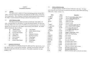
This document compiles a comprehensive set of engineering drawings and related technical information for the basic PDP-9 computer system. It begins by outlining general drawing conventions and providing a "Signal Mnemonic Index" that lists various signals, their origins, and descriptions.
The bulk of the document is organized into several key sections of engineering drawings:
- System Drawings: General assembly illustrations for the PDP-9.
- Central Processor Drawings: Detailed schematics covering the CPU unit assembly, register configurations, special modules, operand fetch and execution flows, break flow, key flow, control module lists, MC switch configurations, clock, run, and display circuits, timing diagrams, instruction registers, operate control, link control, CM timing, CM addressing, CM wiring matrices, and CM sense flip-flops.
- Core Memory System Drawings: Visuals for memory unit assembly, memory parts lists, memory control, timing chains, input mixers, digit drive bits, word selection, sense amplifiers, memory power, Mem/Am cable connections, module utilization, and MC switch configurations.
- I/O Control Drawings: These include diagrams for I/O unit assembly, I/O bus assembly, I/O configurations, I/O bus interfaces, I/O control logic, I/O cables, module utilization, and external components lists, alongside timing diagrams for reader, punch, and teletype operations.
- Reader/Punch Drawings: Specific assembly details, wiring lists, and block schematics for the reader and punch peripherals.
The document serves as an essential technical reference, featuring detailed schematics, assembly diagrams, parts lists, signal definitions, and timing diagrams necessary for the understanding, assembly, and maintenance of the PDP-9 system. It also includes specific engineering specifications for installation and adjustment procedures, such as for the EMI memory stack and core memory.
Site structure and layout ©2025 Majenko Technologies