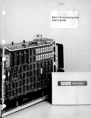
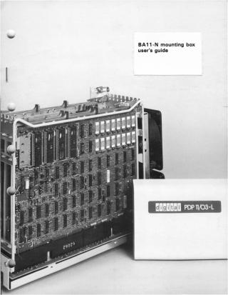
BA11-N Mounting Box User's Guide
Order Number: EK-BA11N-UG
This user guide, published in January 1978, provides instructions for the unpacking, installation, operation, and configuration of the BA11-N Mounting Box for Digital Equipment Corporation (DEC) PDP-11/03 and PDP-11/03L computer systems.
Key aspects covered include:
- Description: The BA11-N is a rack-mountable enclosure housing a power supply, cooling fans, and a 9-slot H9273 backplane designed to accept LSI-11 double and quad-height modules. It features either a blank front panel or one equipped with operating switches (AUX ON/OFF, HALT, RESTART) and status indicators (PWR OK, RUN). It supports both 115V and 230V systems.
- Applications: It serves as a mounting box for a complete PDP-11/03L system or as an expander box for existing PDP-11/03 and PDP-11/03L systems, supporting configurations with up to three backplanes interconnected by cables.
Installation: Detailed procedures are provided for:
- Preliminary Checks: Selecting AC voltage, setting specific jumpers on both the H9273 backplane (for CPU event interrupts and quad KD11 CPUs) and the front bezel assembly (for AUX switch functions and indicator control).
- Module Installation/Removal: Emphasizing that this must be done with power off, using extractor handles for quad modules, and adhering to specific slot placements for CPU and other LSI-11 modules.
- Physical Mounting: Instructions for mounting the logic box cover in a standard 19-inch equipment rack and then sliding the logic box base into the cover.
- Power Connections: Various schemes for connecting single or multiple BA11-N boxes to power sources, including expander box power limitations.
Operation: Explanations of the functions of the front panel switches (AUX ON/OFF, HALT, RESTART) and indicators (PWR OK, RUN), as well as the main ON/OFF and voltage selection switches on the rear.
- Configuration Guidelines (Appendix A): A significant portion of the guide details critical considerations for system configuration, including:
- Bus Loading: Rules for AC and DC loading on the LSI-11 bus, with maximum limits for single and multiple backplane systems (e.g., 20-35 AC loads, 20 DC loads total).
- Power Consumption: Recommendations to keep current drawn from power supplies to 70% or less of their maximum rated output.
- Module Placement: Charts and rules for optimal module placement to ensure proper functionality and adhere to bus priority and electrical characteristics.
- Cable Lengths: Specific requirements for inter-backplane cable lengths in multiple-box systems.
The document stresses the importance of adhering to these electrical and physical guidelines to prevent system failures and ensure stable operation, referencing detailed option summary charts for individual module specifications.
Site structure and layout ©2025 Majenko Technologies