H7842 Power Supply Unit Schematics
Order Number: XX-AE89D-11
This document presents a detailed, multi-page schematic diagram for an H7842 Power Supply Unit (PSU). It covers various aspects of the PSU's design, from its initial wiring to complex control circuitry and output regulation.
The document is organized as follows:
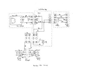
- Page 1 (Rainbow PSU Wiring): Provides a high-level wiring diagram illustrating the physical connections of the PSU, including the mains filter, switch/fan assembly, power input, and outputs to both RH and LH disk drives. It references "PSU H7842".
- Page 2 (H7842 PSU Sheet ① - Startup PSU & Mains Rectifier): Details the primary input section, showing the mains voltage selection (230V/115V), the mains transformer (16-22136-01), rectification circuits, generation of a "Vstart" signal, a "Power OK" signal, and initial "Logic Power" and "Disk/Fan Power" outputs.
- Page 3 (H7842 PSU Sheet ② - Chopper Driver & Chopper): Focuses on the primary switching stage, featuring a "Chopper Driver" and the main "Chopper" circuit, which includes a transformer (16-18498-00) and a power transistor (BUV48A). It also depicts various current sense lines (e.g., Isense 5+, Isense 12+, Isense -12V+), which are routed to the "Control PCB Connections".
- Page 4 (H7842 PSU Sheet ③ - DC Outputs): Illustrates the secondary side of the PSU, detailing the output transformer (16-20387-01) and circuits responsible for generating the regulated DC outputs, including "Raw 12V", "Raw 5V", and a "-12V Regulator" section. Protection features like "Crowbar" circuits and additional current sensing points are also shown.
- Page 5 (H7842 Control Module Sheet ①): Presents the initial part of the control logic, employing multiple comparators (labeled E2a, E2c, E3a, etc.) to monitor the various sense lines, implement a "Current Trip" function, "Soft Start" control, and "Shutdown" mechanisms.
- Page 6 (H7842 Control Module Sheet ② - Chopper Control): Concludes the control section with the "Chopper Control" circuit, built around an SG3527 PWM controller (E4). This circuit integrates the "Soft Start," "Shutdown," "Vstat," and "Power OK" signals to manage the operation of the main chopper, ensuring stable and protected power delivery.
In summary, the document provides a comprehensive engineering blueprint for the H7842 PSU, encompassing its electrical layout, power conversion stages, output regulation, and a sophisticated control system designed for robust operation and protection.
Site structure and layout ©2025 Majenko Technologies