ETCH BOARD ASSY (11/45 CONSOLE)
Order Number: XX-FF1BD-E5
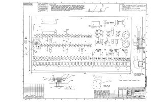
This multi-sheet engineering document provides a comprehensive design and assembly guide for an Etch Board Assembly intended for an 11/45 Console.
Sheet 1 details the physical component layout of the etch board, including knob locations, and provides specific assembly instructions for component alignment (e.g., rotary switch and power lock). It also includes a jumper list and general IC pin location information.
Sheet 2 presents a detailed Bill of Materials (BOM), listing all components necessary for the assembly. This includes a wide range of parts such as resistors, various fasteners (lockwashers, nuts, screws), different types of knobs (switch, dummy, function), a power lock, numerous integrated circuits (DEC 7400, 7404, 7416, 7417, 9318), capacitors, diodes, lamp sockets, lamps, various switches (rotary, momentary, SPDT), connectors, pin housings, and support structures.
Sheets 3 through 6 comprise the electrical schematics of the console board, illustrating its logic and interconnections. These sheets detail the interfaces with external PDR (Processor Data Register) and UBC (Unibus Control) modules. They show the processing of signals from "Switch Register" switches (S1-S18) and various "Control Switches" (S19-S28, S12) through a network of logic gates (e.g., 7400, 7416, 7417 ICs). The schematics define the routing and function of signals for display addressing (KNLA SWR, UBCJ DISP ADRS), status indicators (UBCJ IND), console control (KNLC/KNLD signals), and data selection, including lamp test signals and connections for different operational modes (e.g., KNL/PDR Interface, Signals to/from UBC Module). General notes regarding resistor values, diode types, and grounding practices are also included throughout the schematic diagrams.
Site structure and layout ©2025 Majenko Technologies