MP00326 AN10 Arpanet Interface Engineering Drawings Jul77
Order Number: XX-8F79B-47
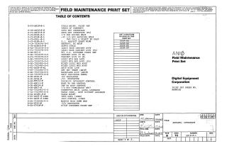
This document is the "ANIØ Field Maintenance Print Set," providing comprehensive technical information for the ANIØ ARPANET Interface unit, with references to AN20. It covers various configurations including AN10-AA, AN10-AB, AN10-BA, and AN10-BB.
The primary purpose of the ANIØ unit is to serve as an ARPANET interface, connecting DECsystem-10 (1090T) and DECsystem-20 (2040T/2050T) hosts to the ARPANET Interface Message Processor (IMP). It supports both local (up to 30 feet) and distant (up to 2000 feet) connections to the IMP.
The document details the unit's hardware components, including:
- Physical Structure: Logic Rack Cabinet Assembly (19-inch), Logic Mounting Box, Wired Logic Mounting Assembly, Backplane Assembly (with rework details), and a Module Hold Down Bar.
- Power & Control: Power Control (861), H7420 Power Supply, and various regulators (+5V, -5V, -15V). Schematics for Power Fail & Select By Pass are also included.
- Interfacing Modules: ARPANET Interface modules, I/O Bus Driver (M664) and Receiver (M564), I/O Bus Terminator (H867), Priority Interrupt Control, Host-to-IMP Control, and IMP-to-Host Control.
- Cabling: A variety of cables are specified, including those for Local Loopback, Distant Loopback, BC10T, BC10K, DC AN10 Harness, and AC Wiring Harness. Wire lists provide detailed connections.
- Logical Modules: IBUS Data (IOBD) and IBUS Control (IOBR). Several Wire Wrap Modules (M8612, M8613, M8614) and Spare ICs are also listed.
- User Interface: AN10 Indicator Panel.
Beyond hardware, the print set outlines key functional and operational aspects:
- Register Formats: Detailed descriptions for Output (OCSR, ODR, OWAR, OVAR) and Input (ICSR, IDR, IWAR, IVAR) control, data, word count, and vector address registers, as well as KL10 API Format.
- System Architecture: Functional block diagrams illustrate the overall system architecture, while flow diagrams (e.g., IMP to Host, Host to IMP) describe operational sequences.
- Timing & Signals: Handshake (four-way, two-way) and PDP-10 I/O Bus timing diagrams, along with host cable signal definitions, ensure proper system interaction.
Finally, the document provides essential procedures for deployment and quality assurance:
- Installation: A comprehensive guide for installing the AN10 Interface Option.
- Testing: Detailed Acceptance Test Procedures and Manufacturing Test Procedures for both AN10 and AN20, including specific steps for module assembly, preliminary checks, online check-out, and delay checks, with expected pulse widths and values.
Related Documents
| Power Control 861 Engineering Drawings | B-DD-861-0 |
Site structure and layout ©2025 Majenko Technologies