MP0 NIA20 Engineering Drawings Dec84
Order Number: XX-2A492-AE
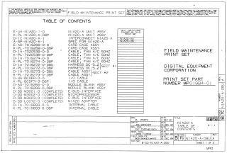
This document is a Field Maintenance Print Set (MPO1984-01) for the Digital Equipment Corporation NIA20-A system, also referred to as NIA20-A (KL10-E). It details the installation procedure for the NIA20 Network Interconnect Adapter into a KL10-E system.
The document includes:
- A Table of Contents listing various components and cables for the NIA20-A system (NIA20-A Unit Assy, card cage, fan cables, DC harnesses, I/O cables, module blanks, microprocessor, E-bus/C-bus interfaces, and internal cables).
Engineering Specifications for the installation, covering:
- Overview and parts list.
- Unpacking and checkout procedures.
- Required equipment for installation and checkout.
- Detailed installation steps for backplane wire adds, port modules, power supply regulator, card cage/internal cable, current limiter, harnesses, and KL10 Adapter Board.
- Checkout procedures post-installation.
Detailed schematics and diagrams for various components and interconnections, including:
- The overall system layout (rear and front views of NIA20 in KL10-E).
- Harness and cable interconnection diagrams.
- Pinout and wiring tables for different cables and modules (e.g., NIA20-A Unit Assy, Fan AC 50/60Hz cables, Harness DC-5.2 Sect N1-1/2, I/O cable, NIA20 Adapter, Voltage Monitor Board, Vane Switch Harness, Backpanel CI20, Current Limiter).
- Printed circuit board (PCB) drill & etch drawings and etch cut drawings for various modules (M3001 EBUS, M3002 MPROC, M3003 CBUS, L0072 NIA, Voltage Monitor Board, Current Limiter, IPA20-L Backplane).
- Block diagrams and logic schematics for the M3001, M3002, M3003, and L0072 modules, detailing control logic, memory, MVR/FMTR, parity, and interface connections.
The document emphasizes confidentiality, proprietary rights, and federal copyright protection. It also contains revision history and lists of personnel involved in its creation.
Related Documents
| DEC STD 186 Signal Integrity | EL-00186-00 |
Site structure and layout ©2025 Majenko Technologies