KC10 ConsoleDescription
Order Number: XX-0EE19-BB
This document provides a comprehensive overview of the JUPITER System Console hardware and its programming.
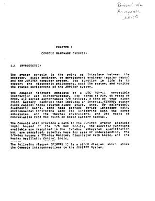
1. Console Hardware Overview: The JUPITER system console acts as the primary interface between the operator/engineer and the JUPITER computer system. Its main functions include supporting diagnostic operations, booting the system, and monitoring the system's environment.
Key hardware components of the console include:
- A DEC PDP-11 compatible microprocessor (based on the F-11 chip set).
- 64K words of RAM, 6K words of PROM, and 256 words of non-volatile CMOS RAM (with battery backup).
- Six serial asynchronous I/O devices.
- A time-of-year clock with an interval timer and battery backup.
- Interfaces for system clock control, diagnostic paths, mass storage devices (RL02 disk drives), and environmental monitoring (power and thermal).
The console interacts with JUPITER-specific logic housed in an I/O Box module, which includes a TTL-Bus Monitor, Diagnostic Path Logic, and Master Oscillator Control Logic.
The console's primary goals (RAMP objectives) are to ensure Reliability, Availability, Maintainability, and Performance through:
- Error detection and logging (CPU, console memory parity, soft error correction).
- Remote diagnosis capabilities.
- I/O-Bus monitoring.
- Extensive loopback capabilities for all console devices and interfaces.
- Environmental monitoring (temperature, airflow, power supply).
- Module isolation diagnostics.
- Software support for these features and error recovery.
It requires external components like a VT100 or LA38 terminal and two RL02 Disk Drives to operate. Notably, the console subsystem is optimized such that it's not fully software-compatible with existing PDP-11 based systems or off-the-shelf operating systems.
2. System Console Description - Hardware Details: The console's heart is the F-11 chip set, consisting of:
- Data Chip: Handles arithmetic/logical functions, data/address transfers (except relocation), and interchip communication.
- Control Chip: Contains microprogram sequence logic and storage for macroinstruction emulation.
- MMU Chip (Memory Management Unit): Provides memory management (address relocation, protection, error detection) and expands addressing capabilities up to 124K words (64K RAM, 4K PROM, 4K I/O space).
Communication within the F-11 chip set uses a time-multiplexed Microinstruction Bus (MIB) and Data Address Lines (DAL).
Other key hardware interfaces and features detailed include:
- Power-On Address (PWR-ON ADR) Buffer: Defines power-up options, halt behavior, and power level conditions.
- Service Logic: Handles prioritized service information (power-up, control errors, memory management aborts, bus/parity errors, power-fail, various interrupt requests).
- Interrupt Vector (INT VECT): Manages interrupt requests from console devices, I/O Box, and RL02 disk drives.
- Console Panel Interface (CPI): Consists of five switches (Power On, Control, Console Lock, System Start, Console Start) and three LED indicators (TTL On, Klinik, Keep Alive) for user interaction and system status.
- Console Memory: Features 64K x 18 Dynamic RAM with byte parity for data integrity.
- Maintenance Registers (MTERR0, MTERR1): Log error addresses and control/status bits for diagnostic purposes.
- Diagnostic Control Register (DIAG CR): Enables loopback features on the console module.
- Diagnostic Scan Port Select (DIAG SCAN PORT SEL): Used with the Diagnostic Scan path for loading Port Microcode and visibility into Port logic.
- RLB Interface: Provides a DMA path between the RL02 Disk Drives and console memory, managed by RLV-11 modules.
- Serial Line Units (SLU): Implemented using Zilog Z80-SIO chips, providing six asynchronous EIA RS232C and RS422/3 lines for various communications (EMM, CTY, KLINIK, VTxxx, DNxxx, Interconsole).
- Time of Year (TOY) Clock: A programmable interrupt timer and Time of Day clock with battery backup.
- I/O Box Interface: Handles communication between the console module and the I/O Box, exposing 192 16-bit registers to the console.
3. Console Hardware Programming: The document also touches on how the console interfaces with the JUPITER-TTL bus, allowing it to request interrupt service, pass information, and access memory. The F-11 processor's Program Status Word (PSW) defines its operational mode (Kernel, Supervisor, User) and priority levels for interrupts. Various registers associated with RL02 Disk Drives, Serial Line Units, Time of Year Clock, and the I/O Box are addressable and programmable for system control and diagnostics.
Site structure and layout ©2025 Majenko Technologies