4380723 Digital Velocity Servo Jun79
Order Number: XX-0E115-2F
This patent describes a digital velocity servo system for precisely controlling the speed of an electric motor. It aims to overcome limitations of prior art frequency-to-voltage converters, such as instability due to temperature changes and component aging, and system complexity.
The system operates as follows:
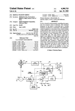
- Speed Sensing: A tachometer connected to the motor converts its rotational frequency into a varying frequency waveform.
- Waveform Conversion: A peak detector converts the tachometer's analog output into a stable square-wave signal.
- Signal Processing for Control:
- This square-wave signal is sent directly to one input of an exclusive-OR (XOR) gate.
- The same square-wave signal is also fed into a shift register, which delays the signal by a precise, predetermined time interval (controlled by a stable reference frequency, e.g., from a system clock). The delayed signal is then sent to the second input of the XOR gate.
- Motor Control Signal Generation: The XOR gate produces a new square-wave output whose duty cycle is proportional to the motor's speed. The pulse width of this output is equal to the shift register's delay, and its frequency is proportional to the motor's speed.
- If the motor speed is at the desired rate, the duty cycle is 50%.
- If the motor speeds up, the duty cycle increases above 50%.
- If the motor slows down, the duty cycle decreases below 50%.
- Motor Actuation: This variable duty cycle signal can then be:
- Integrated by a low-pass filter and amplified to provide a DC voltage that drives the motor.
- Alternatively, directly amplified and applied to the motor.
The core innovation lies in using the combination of a shift register with a stable clock and an XOR gate to perform the frequency-to-voltage conversion, providing a simple, accurate, and temperature-independent speed control mechanism. The system also includes provisions for braking.
Site structure and layout ©2025 Majenko Technologies