W841
Order Number: XX-C5D83-B9
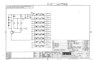
This document is an electrical schematic for a Cable Terminator W841, copyrighted in 1967 by Digital Equipment Corporation.
Key information includes:
- Purpose: Furnished for test and maintenance purposes; the circuits are proprietary.
- Circuit Diagram: Features a network of diodes (D1-D23), resistors (R1-R5), capacitors (C1-C5), and a transistor (Q1), with various labeled input/output connections (A-V, GND, -15V) and corresponding wire colors (Blue, Red, Green, White, Silver, Black).
Parts List: Provides detailed specifications and part numbers for all components, including:
- Transistor Q1 (TSTR. DEC6534B or DEC3638B)
- Resistors R5 (22 Ohm), R1-R4 (1.5K Ohm)
- Diodes D6-D23 (DIO. D664) and D1-D5 (DIO. D662)
- Capacitors C1, C3-C5 (.01MFD 100V) and C2 (3.9MFD 10V)
Transistor & Diode Conversion Chart: Lists DEC and EIA equivalent part numbers for common components.
- Metadata: Drawn by M. Haller and engineered by C.S. Fisk on 12-12-1967. The document is at Revision C, with the main number being CS W841-0-1.
Site structure and layout ©2025 Majenko Technologies