W702
Order Number: XX-73DAF-31
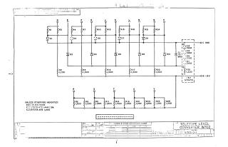
This document is a schematic diagram for a Teletype Level Converter, model W702 (part number W702-0-1), designed by Equipment Corporation of Maynard, Massachusetts.
The circuit primarily features:
- Numerous resistors (R1 through R26) with specified values (e.g., 1,000, 1,200, 1,500 ohms), rated at 1/4W with 5% tolerance unless otherwise indicated.
- Multiple diodes (D1 through D14), which are type D364 unless specified.
- A single capacitor (C1, 0.01 MFDI).
- Various input/output points labeled D through P, and R through V.
- Power connections for C GND (Ground), -OB -15V, and -3V STRATE.
The document also includes a partially empty "Transistor & Diode Conversion Chart."
Site structure and layout ©2025 Majenko Technologies