W533
Order Number: XX-A5755-A8
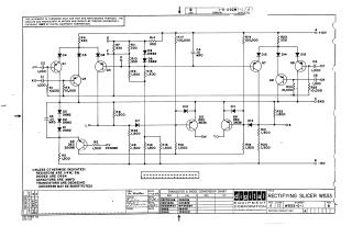
This document is a proprietary circuit schematic for the "Rectifying Slicer W533", designed by Digital Equipment Corporation and copyrighted in 1967.
Key information includes:
- Purpose: The schematic is provided solely for test and maintenance purposes.
- Circuit Details: It depicts a complex electronic circuit featuring numerous transistors (e.g., DEC 3009B, DEC 3639, DEC6534D), diodes (e.g., D662, D664), resistors, and capacitors.
- Power and Signals: The circuit operates with +10V, -15V, and ground connections, and includes various input signals (JO, KO, STROBE) and output/test points (OP, OR, OS, L, OM, TO).
- Component Specifications: General notes specify resistors as 1/4W 5%, diodes as D664 (unless otherwise indicated), capacitors as MMFD, and transistors as DEC6534D (with DEC6534B as a substitute).
- Conversion Chart: A table provides a cross-reference for Digital Equipment Corporation's transistor and diode part numbers to their EIA equivalents (e.g., DEC3009B corresponds to 2N3009, D662 to IN645).
- Revision History: The drawing is identified as W533-0-1, Revision B (Printed Circuit Rev. A), with drawing and check dates in January 1967.
Site structure and layout ©2025 Majenko Technologies