W250
Order Number: XX-C04B7-2E
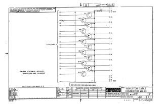
This document is a schematic diagram for an Indicator Cable Connector, model W250-0-1, Revision B, developed by Digital Equipment Corporation in 1966.
Key features include:
- Purpose: Furnished for test and maintenance purposes only, the circuits are proprietary.
- Circuitry: It illustrates a flexible printed circuit (FLEXPRINT) connecting various input/output lines (labeled A, B, C GND, D through U, V GND) to 12 transistors (Q1-Q12) and a 0.01 MFD capacitor (C1).
- Components: Unless otherwise indicated, the transistors are model DEC6534D, which is equivalent to MPS6534 according to the provided conversion chart.
- Identification: The associated parts list is A-PL-W250-0-0, and the printed circuit revision is AB.
- Dates: The schematic was drawn, checked, and engineered in November 1966.
Site structure and layout ©2025 Majenko Technologies