W051
Order Number: XX-E23C2-EB
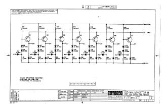
This document is an electronic schematic for a "100 MA Indicator & Relay Driver", identified as WO51-0-1, Revision E, designed by Digital Equipment Corporation and copyrighted in 1964.
Key points from the document include:
- The schematic is proprietary and furnished only for test and maintenance purposes.
- It illustrates a circuit with seven distinct driver stages (Q1 through Q7), each likely designed to control an indicator or a relay, with outputs labeled OD through OT.
- General component specifications state that resistors are 1/4W, 10%, and transistors are DEC 6534B (equivalent to MPS6534).
- A conversion chart provides equivalent part numbers for diodes: D662 (IN645) and D664 (IN3606).
- The circuit operates with +10V, Ground, and -15V power rails.
Site structure and layout ©2025 Majenko Technologies