W040
Order Number: XX-608D1-E8
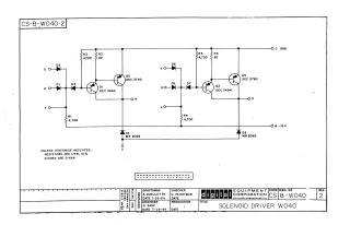
This document is an electrical schematic for a Solenoid Driver circuit, specifically designated as CS-B-W040, designed by Digital Equipment Corporation in July 1964.
The circuit features two independent driver channels, each designed to control a solenoid:
- Input Stage: Each channel has multiple diode inputs (D, E, F for the first channel; J, K, L for the second), likely forming a logic gate to activate the driver.
- Amplification Stage: A two-transistor amplifier (Q1/Q2 for the first channel; Q3/Q4 for the second) provides the necessary current to drive the solenoid connected to outputs R and S, respectively. Transistors used are DEC 3494 and DEC 3790.
- Protection/Power: Diodes D4 and D8 (MR 2066) are connected to a -15V power supply (B-15V) and common ground (C GND), likely for voltage clamping or flyback protection for the inductive solenoid loads.
- Component Specifications: Resistors are generally 1/4W, 10% tolerance, with specific values indicated. Diodes D1, D2, D3, D5, D6, D7 are D-664 type.
Site structure and layout ©2025 Majenko Technologies