W020
Order Number: XX-7C191-45
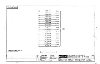
This document is a schematic diagram for an Indicator Cable Connector, model WO20, identified by drawing number CS B-WO20, Revision 1, from Digital Equipment Corporation, dated June 1964.
The diagram illustrates the wiring of 18 individual input lines (labeled A, B, C, D, E, F, H, J, K, L, M, N, P, R, S, T, U, V) to a ribbon cable. Each input line is connected through a 1500 Ohm, 5% tolerance resistor to a specific, color-coded output wire. The color sequence for the outputs is Black, Brown, Red, Orange, Yellow, Green, Blue, Violet, Gray, White, followed by a repetition of Black, Brown, Red, Orange, Yellow, Green, Blue, Violet. A general note indicates that all resistors are 1/4W unless otherwise specified.
Site structure and layout ©2025 Majenko Technologies