S602
Order Number: XX-6BC74-77
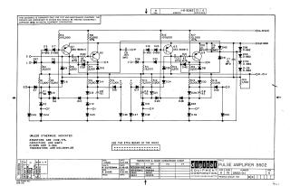
This document is a proprietary schematic diagram for the Pulse Amplifier S602, copyrighted by Digital Equipment Corporation in 1965, and intended for test and maintenance purposes only.
The circuit design includes:
- Four Transistor Amplifier Stages (Q1, Q2, Q3, Q4): Primarily utilizing DEC 3639-C transistors (EIA equivalent: 2N3639).
- Passive Components: A variety of resistors (specified as 1/4W, 5%), capacitors (in MMFD), and diodes (D-662/IN645 and D-664/IN3606).
- Power Supplies: The amplifier operates with A+10V, C,N Ground, and B-15V.
- Connection Points: Several labeled input/output or test points are present (e.g., D, L, E, M, V, H, P, O, R, S, J, F, T).
- Manufacturing Note: The design specifies the use of the R602 etch board.
The document also provides a transistor and diode conversion chart with DEC and EIA equivalents, along with a revision history.
Site structure and layout ©2025 Majenko Technologies