S151
Order Number: XX-E9305-39
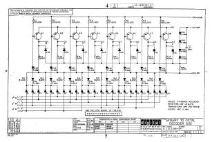
This document is a schematic diagram for a Binary to Octal Decoder, model S151, designed by Digital Equipment Corporation (DEC) and copyrighted in 1965.
The schematic illustrates a circuit that converts binary input signals (indicated by 2⁰ FF, 2¹ FF, and 2² FF lines) into one of eight distinct octal outputs (00 through 07). The circuit utilizes eight NPN transistors (Q1-Q8) as primary switching elements, along with a complex arrangement of diodes (D1-D24 for input decoding, plus others for biasing and output) and various resistors. Power is supplied at +10V and -15V.
Key component specifications are provided, including resistors rated at 1/4W, 5%, transistors as DEC 3639B (EIA equivalent 2N3639), and diodes as D-662 (1N645) or D-664 (1N3606). The document states that the schematic is furnished solely for test and maintenance purposes and that the circuits are proprietary.
Site structure and layout ©2025 Majenko Technologies