R203
Order Number: XX-E23A6-00
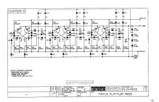
This document is an electrical schematic, drawing number CS B-R203 Revision 3, titled "TRIPLE FLIP-FLOP R203".
It illustrates three distinct flip-flop circuits, each constructed using:
- A pair of NPN transistors (DEC 36390).
- Numerous diodes (primarily D-662 and D-664 types).
- Various resistors (specified as 1/4W, 5% tolerance, with values ranging from 1,500 to 100,000 ohms).
- Capacitors (specified in MMFD, with values like 0.01 and 100).
The circuit operates with +10V (A), -15V (B), and ground (OC GND) power rails. Standard component specifications (e.g., resistor wattage/tolerance, capacitor units, specific diode and transistor part numbers) are provided. The schematic was drafted by A. Ouellette for Digital Equipment Corporation in June/July 1964.
Site structure and layout ©2025 Majenko Technologies