R151
Order Number: XX-257A6-8B
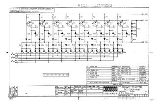
This document is a schematic diagram for a Binary to Octal Decoder, identified as R151.
Key points:
- Purpose: The schematic illustrates the circuit design for test and maintenance purposes, noting its proprietary nature and copyright by Digital Equipment Corporation (DEC) in 1964.
- Components: The circuit primarily consists of eight transistor stages (Q1-Q8, identified as DEC3639B/2N3639), a network of resistors (R1-R25, with values from 1.5K to 100K ohms), various diodes (D1-D52, using D662/1N645 and D664/1N3606 types), and one capacitor (C1, 0.01 MFD).
- Functionality: It's designed to convert binary input signals (indicated by multiple input lines D1-D24) into one of eight octal outputs (labeled M through V, corresponding to 00 through 07).
- Power: The circuit operates with a +10V, -15V, and ground reference.
- Supporting Information: The document includes a comprehensive parts list with reference designations, descriptions, and part numbers, as well as a transistor and diode conversion chart between DEC and EIA designations.
Site structure and layout ©2025 Majenko Technologies