R113
Order Number: XX-6A303-F1
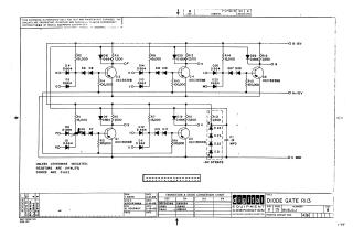
This document is a schematic diagram for a "DIODE GATE RI13" logic circuit, copyrighted in 1965 by Digital Equipment Corporation.
Key aspects of the document include:
- Purpose: It is furnished for test and maintenance purposes, with the circuits explicitly stated as proprietary.
- Circuit Components: The design primarily features transistors (DEC3639B, equivalent to 2N3639), various diodes (D662, equivalent to IN645; and D664, equivalent to IN3606), and numerous resistors (specified as 1/4W, 5% tolerance unless otherwise indicated). A single capacitor (C1, 0.01 MFD) is also present.
- Inputs/Outputs & Power: The schematic shows multiple input points (e.g., DO, EO, HO, JO, LO, MO, PO, RO, TO, UO), internal nodes (F, K, N, S, V), and connections to power supplies (B-15V, A+10V, C GND, and -3V STRATE).
- Specifications: General specifications state resistors are 1/4W, 5% and diodes are D662 unless otherwise indicated. A "Transistor & Diode Conversion Chart" provides EIA equivalents for the DEC part numbers.
- Administrative Details: The document includes a revision history (Rev B shown), and details about the drafter, checker, and engineer, with dates from February 1965.
Site structure and layout ©2025 Majenko Technologies