M956
Order Number: XX-413EA-C9
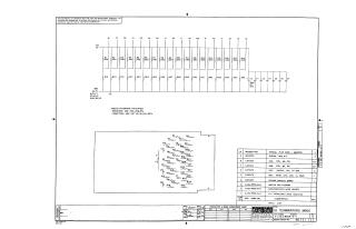
This document is a proprietary schematic diagram from Digital Equipment Corporation, copyrighted 1970, for a circuit titled "18 TERMINATORS M956" (Part Number M956-0-1, Revision A). It is intended for test and maintenance purposes only.
The main schematic illustrates a termination network connecting 18 input/output points (e.g., B1, D1, E1) to a +5V supply (A2) and Ground (GND). This network primarily consists of:
- 36 Resistors: Many are specified as 220 ohms. The default value, unless otherwise indicated, is 330 ohms, 1/4W, 5%.
- Several Capacitors: One is specifically a 39 µF, 10V, 10% Solid Tantalum capacitor (C3). The default value, unless otherwise indicated, is 0.047 µF, 16V, 50-20%.
A second, more detailed schematic section is also present, showing another network of resistors and capacitors, likely a sub-circuit or detailed breakdown.
A comprehensive parts list specifies the components required for this assembly, including:
- 18 Resistors (330 ohms, 1/4W, 5%)
- 18 Resistors (220 ohms, 1/4W, 5%)
- 6 Capacitors (0.047 µF, 16V, 50-20%)
- 1 Capacitor (39 µF, 10V, 10% Solid Tantalum)
- 1 Etched Circuit Board
- 1 "HANDLE, FLIP CHIP - MAGNETA"
- Various other assembly-related items like eyelets and documentation for module history and layout.
The document was drawn by L. Cooper on December 4, 1970, and checked/approved on January 12, 1971.
Site structure and layout ©2025 Majenko Technologies