M950
Order Number: XX-F2FB6-32
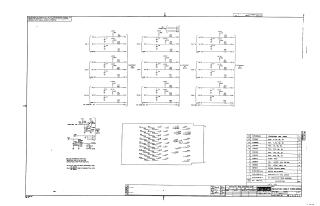
This document is an electrical schematic diagram for the Digital Equipment Corporation "Indicator Cable Conn M950" module (part number M950-0-1), copyrighted in 1970 and intended for test and maintenance purposes.
The schematic details:
- Nine individual switch and lamp indicator circuits (SW1 through SW9), each comprising Normally Open (NO) and Normally Closed (NC) connections, an indicator lamp, associated resistors, and capacitors, primarily operating at +3.5V.
- A dedicated +5V "Lamp Test" circuit featuring a transistor (Q1), diodes (D1, D2), resistors, and capacitors.
- Connections to an external module (M949) via "Flexprint."
- General notes specifying standard resistor (4.7K, 1/4W, 5%) and capacitor (470pF, 100V, 5%) values, and clarifying "FA" (etch side of M950, component side of M949) and "FB" (component side of M950, etch side of M949) board designations.
- A comprehensive parts list including transistors, resistors, capacitors, diodes, and the etched circuit board itself.
- A transistor and diode conversion chart, and revision history.
The document emphasizes its proprietary nature and the need for appropriate handling.
Site structure and layout ©2025 Majenko Technologies