M947
Order Number: XX-89B88-EA
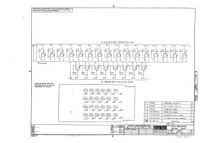
This document is a schematic diagram for the KI-IO INDICATOR DRIVER M947 module, produced by Digital Equipment Corporation.
Here's a summary of its key aspects:
- Purpose & Disclaimer: The schematic is provided for test and maintenance purposes only and contains proprietary information, copyrighted 1970 by Digital Equipment Corporation.
Module Identification:
- Title: KI-IO INDICATOR DRIVER M947
- Number: M947-0-1, Revision B
- Drawn by: Nancy Moore
- Date: May 18, 1970
Circuit Components:
- The circuit primarily consists of 24 transistors (Q1-Q24) and 24 capacitors (C1-C24), along with two diodes (D1, D2).
- General Specifications: Unless otherwise indicated, capacitors are 470pF, 100V, ±5%, and transistors are DEC6531B.
- A Transistor & Diode Conversion Chart indicates that DEC6531B transistors can be cross-referenced with MPS6531 (EIA).
Physical Layout Indication: The schematic shows connections grouped by "FA" and "FB".
- "FA" refers to connections on the "ETCH SIDE OF M947; COMPONENT SIDE OF M948".
- "FB" refers to connections on the "COMPONENT SIDE OF M947; ETCH SIDE OF M948". This suggests a multi-layer or multi-board assembly.
Parts List: Confirms the use of:
- 24 Transistors (DEC 6531B)
- 24 Capacitors (470 PF 100V 5%)
- 1 Etched Circuit Board (M947)
- It also references related documents such as Module ECO History, Assembly/Drilling Hole Layout, and X-Y Coordinate Hole Location.
Site structure and layout ©2025 Majenko Technologies