M7820
Order Number: XX-1268F-FD
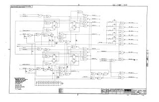
This document is an electrical schematic for the Digital Equipment Corporation (DEC) INTERRUPT CONTROL M7820 module, copyrighted in 1970.
The schematic details the logic circuits responsible for managing system interrupts. It features two primary interrupt channels, labeled 'A' and 'B', each with dedicated input signals for interrupt requests ('INT A H', 'INT B H'), enable/disable control ('INT ENB A H', 'INT ENB B H'), and master clear functionality.
Key features and components include:
- Bus Interface Logic: Extensive connections to various bus signals such as 'BUS BR A L' (Bus Request A), 'BUS SACK L' (Bus Sack), 'BUS BBSY L' (Bus Busy), 'MASTER A L', and similar lines for channel B, indicating its role in bus arbitration and communication.
- Data Bus Interaction: Direct connections to 'BUS D08 L' through 'BUS D02 L' suggest the module is involved in transferring data, possibly interrupt vector information, via the system's data bus.
- State Management: Utilizes D-type flip-flops (e.g., E13 FFA1/FFA2 for channel A, E4 FFB1/FFB2 for channel B) to maintain the state of interrupt requests, grants, and other control signals.
- Output Signals: Generates a main 'BUS INTR L' signal to the system, and 'INTR DONE A H'/'INTR DONE B H' signals to acknowledge interrupt processing completion. 'BG OUT A H' and 'BG OUT B H' are likely bus grant outputs.
- Logic Gates: A variety of NAND, NOR, and other gates (DEC7400, DEC7402 series) are used for combinatorial logic and signal conditioning.
The circuit operates on a +5V power supply and employs TTL (Transistor-Transistor Logic) integrated circuits from the DEC8881, DEC7400, DEC7474, and DEC7402 families, along with specific transistors (DEC30098) and a variety of resistors and capacitors.
The document explicitly states it is proprietary and furnished "ONLY FOR TEST AND MAINTENANCE PURPOSES."
Site structure and layout ©2025 Majenko Technologies