M629
Order Number: XX-33C98-83
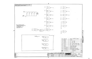
This document is a proprietary schematic titled "BUS DRIVERS M629" (part number M629-0-1), copyrighted in 1970 by Digital Equipment Corporation. It is provided for test and maintenance purposes only.
The schematic details a digital logic circuit utilizing NAND gates from three DEC 8881 integrated circuits (E1, E2, E3) and one DEC 7400 integrated circuit (E4). The circuit operates on a +5V supply, with standard IC power pin assignments (Pin 7 Ground, Pin 14 +5V).
Key components shown include:
- Four 0.01uF, 100V, 20% capacitors (C1-C4).
- One 35uF, 10V, 10% capacitor (C5).
- Inputs labeled K2, B1, C1, D2, E2, R2, F2, H1, L1, K1, P2, N2, S2, R1, U2, V2.
- Outputs labeled L2, A1, D1, E1, F1, M1, H2, J2, M2, P1, N1, among others.
A parts list confirms the use of three DEC 8881 ICs, one DEC 7400 IC, four 0.01uF capacitors, and one 0.39uF S. Tantalum capacitor (noting a discrepancy with the 35uF C5 value labeled on the schematic). The list also includes mechanical components like a magenta 'Flip Chip Handle' and eyelets, along with the etched circuit board itself. The drawing was created by R. Cooper on December 14, 1970.
Site structure and layout ©2025 Majenko Technologies