M511
Order Number: XX-A9F03-89
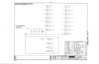
This document is a proprietary schematic diagram (M511-0-1, Rev A) for a "Positive Bus Receiver M511" module, copyrighted by Digital Equipment Corporation in 1970. It is intended solely for test and maintenance purposes.
The circuit primarily consists of four DEC 380A integrated circuits, each containing multiple logic gates, with power supplied at +5V to Pin 8 and ground at Pin 1 for each IC. Decoupling capacitors are used, with most being .01uF, 100V, 20% (disk), and one 39uF, 10V, 10% (tantalum) capacitor (C5).
The accompanying parts list details the components, including the four DEC 380A ICs, five capacitors (four .01uF and one 39uF), an etched circuit board, and various assembly or documentation items.
Site structure and layout ©2025 Majenko Technologies