M502
Order Number: XX-302FC-24
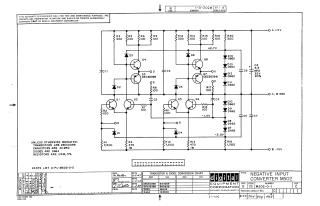
This document is a circuit schematic for a "Negative Input Converter M502," copyrighted in 1967 by Digital Equipment Corporation (DEC). It is explicitly stated that the schematic is for test and maintenance purposes only, and the circuits are proprietary.
The schematic details the internal electronic design, operating with +5V and -15V power rails and a common ground. It features eight transistors (Q1-Q8), numerous diodes (D1-D14), resistors (R1-R20), and capacitors (C1-C8).
Key component specifications are provided:
- Transistors: Generally DEC3009B, with specific ones like Q3 and Q7 being DEC3639B.
- Capacitors: Generally 0.01 MFD, except for C8 (6.8 MFD, 35V, 20%).
- Diodes: Generally D664, with many also specified as D662.
- Resistors: Generally 1/4W, 5% tolerance, with R4 and R13 specified as 1W.
The document includes a "Transistor & Diode Conversion Chart" that provides EIA equivalents for DEC part numbers (e.g., DEC3009B = 2N3009, D662 = 1N645). It also shows a revision history (up to Rev C, dated August 1972) and references a parts list (A-PL-M502-0-0). The initial drawing and checking dates are from June 1967.
Site structure and layout ©2025 Majenko Technologies