M501
Order Number: XX-71C46-41
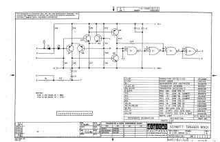
This document is a schematic diagram for a Digital Equipment Corporation (DEC) Schmitt Trigger M501 circuit, copyrighted 1968. It is explicitly noted as being for test and maintenance purposes and contains proprietary circuit information.
The document features:
- A circuit diagram detailing various transistors (e.g., DEC4258, DEC3009B-S), diodes (D664), resistors, capacitors, and integrated circuits (DEC7400N logic gates), all connected to a +5V power supply and ground.
- A detailed parts list providing reference designations, component descriptions (including values and tolerances), and DEC part numbers for all components (e.g., Resistors R13, R14 are 180 Ohm 1/4W 10% CC).
- A transistor and diode conversion chart cross-referencing DEC part numbers with EIA equivalents (e.g., D664 to IN3606, DEC3009B to 2N3009).
- Notes on integrated circuit pin assignments, specifying Pin 7 for GND and Pin 14 for +5V.
- Administrative details including drawing date (April 1968), revision information (Rev A), and company location (Maynard, Massachusetts).
Site structure and layout ©2025 Majenko Technologies