M405
Order Number: XX-C0A86-3F
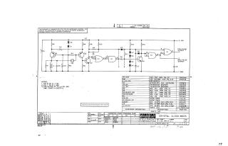
This document is a schematic diagram for the "CRYSTAL CLOCK M405," copyrighted in 1968 by Digital Equipment Corporation. It is explicitly stated as being for test and maintenance purposes and contains proprietary circuit information.
The schematic details an electronic circuit designed to generate positive and negative pulse outputs, likely driven by a crystal (implied by the title and the presence of CRI, which requires an external reference). Key components include:
- Transistors: Q1, Q2 (DEC4258) and Q3, Q4 (DEC4274).
- Integrated Circuit: E1 (DEC7400N, likely a logic gate array).
- Diodes: D1-D8 (D662, D664).
- Passive Components: Resistors (various values), capacitors (various types and values), and an inductor (L1).
Accompanying the schematic are:
- Notes: Indicating power supply connections for the integrated circuit (Pin 14 to +5V, Pin 7 to Ground) and referencing an external drawing (A-00517-2) for specific values of C2, L1, and CRI.
- Parts List: A comprehensive table listing reference designations, descriptions, and Digital Equipment Corporation part numbers for all components.
- Transistor & Diode Conversion Chart: Providing equivalent EIA part numbers for the specified DEC transistors and diodes.
- Drawing Information: Includes the drafter (M. Haller, dated 4-17-68) and engineer (J. Rickett), company (Digital Equipment Corporation), document number (M405-0-1), and revision level (C).
Site structure and layout ©2025 Majenko Technologies