M360
Order Number: XX-92185-E3
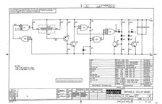
This document is a proprietary schematic diagram for a "Variable Delay M360" circuit, copyrighted by Digital Equipment Corporation (DEC) in 1967. It is explicitly stated that the schematic is for test and maintenance purposes only and that the circuits are proprietary.
The detailed circuit diagram includes:
- A Delay Line 500 (DLDI) as a central component.
- Various integrated circuits (E1, E2), specifically identified as DEC7400N (Quad 2-input NAND) and DEC7440N (Dual 4-input NAND).
- Multiple transistors (Q1, Q2, Q3, Q4), including types DEC6534B and DEC3009B-S.
- Diodes (D1-D7), specified as D664.
- Numerous resistors (R1-R12) with various resistance values (e.g., 1.5K, 3K, 220, 750, 470 ohms, all 1/4W 5% CC).
- Capacitors (C1-C4), including .01 MFD and .330MMF types.
Notes indicate standard power connections for the integrated circuits: Pin 7 to Ground (GND) and Pin 14 to +5V. A comprehensive parts list provides descriptions and part numbers for all components, and a "Transistor & Diode Conversion Chart" offers EIA equivalents for the specified DEC parts.
Site structure and layout ©2025 Majenko Technologies